Form and Function
Images of Bridge
|
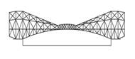
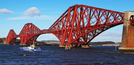
The Fourth Bridge |
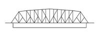
The Big Four Bridge |
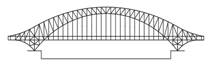
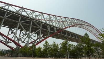
Chaotianmen Bridge |

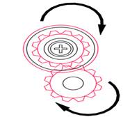
Conceptual Table
|
MOVABLE
ITEMS |
THE MOVING MECHANISM EXTRACTED FROM
EACH ITEM |
The Fourth Bridge
CANTILEVER |
The
Big Four Bridge
TRUSS |
Chaotianmen
Bridge
ARCH |
|
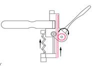
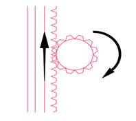
Wine Bottle Opener |
|
Rack and pinion gears can be used as a form of pully mechanism through linear motion in order to open a portion of the bridge. However, you would need to design a pulley system to give the gears motion. This trust design allows for that at its entrance point. |
The existing truss base can be designed as sliding track that converts the rotating movement of the pinion gear into linear causing the bridge to open. In order to achieve this, you would have to increase the height of the structural support at one end of the bridge. |
The shape of the bridge at one end would have to be changed in order to use this type of mechanism. However, the connecting arch would not be structurally sound as the load will cause it to break eventually. |
|
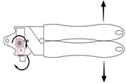
Can Opener |
|
This system can aid in vertical lifts using multiple cables as well as a hinge system to account for the movement of the road. However, the cantilever would have no support when the bridge opens. |
The usage of gears allows precise movement and also reduces the lifting load. Consequently, the moving gears may require a great amount of cables for it to function properly. |
This type of gear system could work well in terms of a vertical lift to open bridge. The arch directly centered above could assist in design of a gear mechanism linked to one end of the bridge for it to open. The weight will still be evenly distributed on each side. |
|
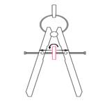
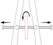
Adjustable Compass |
|
A hinge system can only be used to open the bridge at one end. This will require the addition of more framing members to improve the structural stability. |
The bridge could be hinged at one end and lifted upwards at the other by means of a pulley system. You would have to transform the structural shape to account for the pulley system which will add weight to the road to be lifted up. |
A hinged system can be used to pull the road upwards. However, you have to take into consideration a counterbalance which will transform the shape at one end of the bridge. With a hinge system, this bridge design could only open at the center and no other place due to a lack space for upward movement. |